To perform a continuity test, one must first ensure the multimeter is properly set up. This involves selecting the continuity function, which is usually indicated by a symbol resembling a sound wave or diode on the device. Clear and accurate interpretation of the results obtained during the test is crucial to ascertain the presence or absence of continuity.
Key Takeaways
Multimeter Functions

A multimeter is an essential tool that combines several electronic measurement functions in one unit. Typically, it can measure voltage, current, and resistance. Understanding the functions and settings of a multimeter is crucial for various diagnostic and repair tasks, such as testing for continuity.
Key Functions:
- Voltage Measurement: This allows the user to measure electrical potential difference between two points in an electric circuit. Multimeters have settings for alternating current (AC) or direct current (DC) voltage.
- Current Measurement: It measures the flow of electric charge and generally requires series connection within the circuit. Safety precautions must be observed due to the risk of high current.
- Resistance Measurement: This function measures how much a material opposes the flow of current, expressed in ohms (Ω).
Continuity Testing: A special aspect of resistance measurement, continuity testing checks if the current can flow through a circuit or component uninterrupted. The multimeter emits an audible beep if there is continuity, indicating no breaks in the circuit.
Accuracy Matters: Professional electricians and technicians prioritize multimeters that offer high accuracy and reliable readings.
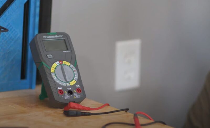
Setup for Continuity Testing:
- Ensure the device is off and the circuit is not live.
- Insert the black test lead into the COM jack.
- Insert the red lead into the VΩ jack.
For those beginning to use a multimeter, learning to navigate these functions is the first step before carrying out any tests. Proper use ensures accurate measurements and safe operation.
Preparing to Test Continuity
Testing for continuity is a fundamental procedure in troubleshooting electrical circuits. Correct preparation ensures safe and accurate measurements.
Safety Precautions
Before starting continuity tests, one must verify all power sources to the circuit being tested are turned off and disconnected. This prevents electrical shock and damage to the multimeter. Wearing safety gloves and safety goggles is recommended to protect against accidental exposure to live circuits.
Selecting the Right Multimeter Settings
One must ensure that the multimeter is set to the continuity setting, symbolized by a series of arcs or a loudspeaker symbol, depending on the model. If a dedicated continuity mode is not available, setting the multimeter to measure resistance (ohms) is the alternative. In this mode, it is important to select a range that can detect a low resistance, often below 200 ohms, which indicates a continuous path.
Conducting the Continuity Test
Conducting a continuity test with a multimeter is a straightforward process to determine if two points are electrically connected. The multimeter measures resistance and indicates continuity when low resistance is detected.
Testing Wires and Cables
To test the continuity of a wire or cable:
- Turn off the power to the circuit.
- Set the multimeter to the continuity setting or to measure resistance (ohms).
- Connect one lead of the multimeter to one end of the wire.
- Connect the second lead to the opposite end of the wire.
- Look for a reading:
- A zero or near-zero resistance indicates good continuity.
- A high resistance reading signifies a break in the wire.
For a visual guide on setting up your digital multimeter, you can refer to comprehensive instructions from Fluke.
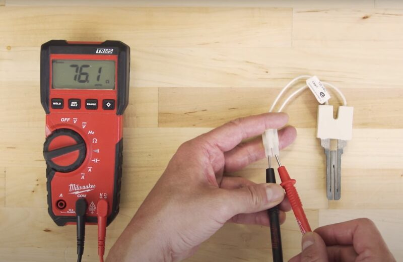
Checking Connectors and Terminals
To test the continuity of connectors and terminals:
- Disconnect any power to avoid false readings or electrical damage.
- Adjust the multimeter to continuity mode or the appropriate resistance range.
- Touch one probe to one side of the connection point.
- Touch the other probe to the corresponding connection point.
- Review the multimeter display for continuity:
- A continuity signal or low ohms reading indicates a proper connection.
- No signal or an infinite resistance reading means there’s no continuity.
Learning how to interpret the multimeter readings is essential, an illustrative example can be found in a YouTube tutorial on continuity testing.
Interpreting Test Results
When using a multimeter for continuity testing, the individual should look for a particular reading on the device’s display. A common multimeter will typically show either a numeric value or a visual/auditory signal if continuity is present:
- Zero or Near-Zero Resistance: This indicates that the circuit is complete, and electrical current can flow freely between the points being tested.
- Beeping Sound: Many digital multimeters have an audible feature that emits a beep when continuity is detected, simplifying the testing process.
- Infinite Resistance or ‘OL’: This reading suggests there is a break in the circuit, indicating no continuity.
Your test results can vary based on the specific components or wiring being tested. Here is a brief outline to decode the readings:
| Display Indication | Interpretation |
|---|---|
| 0 – 1Ω | Good continuity |
| Audible Tone | Continuity present |
| OL or 1 | Open circuit (no continuity) |
Troubleshooting Common Issues
When encountering issues with continuity testing using a multimeter, the user may need to assess several common problems.
Incorrect Mode: Ensure the multimeter is set to the continuity setting, usually represented by an icon resembling a sound wave or diode symbol.
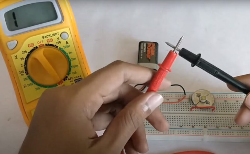
Faulty Test Probes: Test for malfunctioning probes by touching them together. If there’s no continuity sound or expected reading, they likely need replacement.
Dead Battery: A low or dead battery may cause erratic multimeter behavior. Replace the battery with a fresh one and test the device again.
Contaminated Probe Tips: Dirty or oxidized probes can lead to inaccurate readings. Clean the tips with a fine abrasive or alcohol.
Improper Range Selection: Some digital multimeters require selecting a range. Select the lowest resistance range for continuity testing.
Multimeter Makes Continuous Beep: If the multimeter gives a continuous beep even when probes are not touching, it could point to an internal fault.
| Issue | Action to Take |
|---|---|
| Incorrect Mode | Set to continuity mode (sound wave or diode symbol) |
| Faulty Test Probes | Touch probes together to check for beep or reading |
| Dead Battery | Replace multimeter battery |
| Contaminated Probe Tips | Clean with a fine abrasive or alcohol |
| Improper Range Selection | Select lowest resistance range for continuity |
| Continuous Beep | Check for potential multimeter fault |
Frequently Asked Questions
What steps are involved in performing a continuity test with a multimeter?
To perform a continuity test, one must first ensure the circuit is de-energized. Then, set the multimeter to the continuity setting, which is often indicated by a diode symbol. After that, place the probes on either end of the circuit. A continuous circuit will yield a low-resistance reading or produce an audible beep.
What does the continuity symbol look like on a multimeter, and how is it used?
The continuity symbol on a multimeter is typically represented by a diode symbol or a series of arcs forming a sound wave, indicating the audible beep function. When selected, this function allows the user to test the connection between two points without looking at the display constantly.
How can you check the continuity of a cable using a multimeter?
To check the continuity of a cable, one should connect one probe to each end of the cable. If the meter displays a low resistance value or beeps, the cable has continuity. Otherwise, the cable may be damaged or broken.
How is ground continuity verified with a multimeter?
Ground continuity is verified by connecting one multimeter probe to the ground pin of a plug or a metal part of a chassis and the other probe to the end of the ground wire. Continuous ground will show a low resistance reading, indicating that the path to ground is intact.
What constitutes a good versus a bad continuity reading on a multimeter?
A good continuity reading is typically a low resistance value, often below a few ohms, indicating a strong connection. A bad continuity reading is an open circuit, often displayed as ‘OL’ on digital multimeters, signifying no continuity or a very high resistance path.
Can you explain how to perform a continuity test if the multimeter does not have an audible beep feature?
If the multimeter lacks an audible beep for continuity, one must watch the display for a change in resistance when testing. Continuity is confirmed when the resistance reading is very low or near zero, while a high or infinite resistance suggests a lack of continuity.
Conclusion
Continuity testing with a multimeter is a fundamental skill for diagnosing and troubleshooting electrical circuits. Understanding how to properly set up the multimeter, interpret the readings, and apply this knowledge to test for continuity ensures effective maintenance and repair of electrical systems.